FSAE Intake and Exhaust Design
December 2019 - May 2020
I redesigned both the intake and exhaust of the car in an effort to gain better engine performance from the powertrain system. Using results from Ricardo WAVE parametric simulations to set constraints for the design geometry, both subsystems underwent extensive changes. I modeled these new systems in SolidWorks and also completed some of the manufacturing of the parts included in these systems.
Intake Design
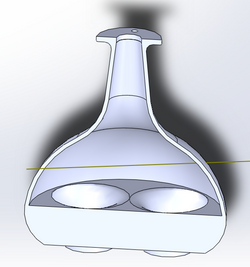
The intake design was changed from a side-oriented Venturi to a vertically-oriented Venturi. The main reason driving this change was to get a more symmetric flow of air from the plenum, through the four runners, to each of the four engine cylinders.
CFD and Ricardo WAVE analysis results determined a range of ideal plenum volumes and runner lengths which drove the new design. A second design constraint was imposed by the chosen methods of manufacture of the system components. We outsourced the plenum to be 3D-printed from glass-infused nylon, so its design needed to be something compatible with the 3D-printing process. The four runners were machine-bent aluminum, also outsourced by our team. As a result, the design needed to adhere to the constraints of their bending process: the outer and inner diameters of the tubes were constrained, as well as the spacing between bends, and the bend radii themselves.
Incorporating all of these various constraints into the design, along with a general idea of the desired plenum shape was the real challenge. Ultimately, a final design was reached which adhered to every single constraint imposed by the various sources described above.
Finally, manifold air pressure (MAP) and temperature sensors needed to be inserted into the plenum to monitor the state of the air inside it. The plenum design was updated accordingly, with plans for the attachment bungs to be manufactured in-house from aluminum.
SolidWorks Model of Intake Manifold
 |  |  |  |
|---|
Exhaust Design
The redesign of the exhaust system followed a similar procedure to that of the intake. The main goal of the exhaust redesign was to significantly reduce the number of welded components in the system.
CFD and Ricardo WAVE analysis results were again used to determine an optimal range of lengths of the primary, secondary, and tertiary runners in the 4-2-1- exhaust design. As with the intake, we outsourced the machine bending of the exhaust tubing. So, I was limited by the same bending constraints Additionally, we purchased the collectors that facilitate the 4-2-1 transitions, constraining another element of the overall system geometry.
Within the imposed constraints, the final exhaust system was designed. Notable deviations from the previous design were shorter primary lengths, allowing for more space in the rear of the car, below the engine block, and a significant reduction in the individual components that make up the assembly.
SolidWorks Model of Exhaust Manifold

Manufacture and Assembly
We outsourced the intake plenum to be 3D-printed, with the intake runners custom bent from aluminum tubing. The injector block used to interface with the engine block was also manufactured by another firm. We bought a commercially available throttle body and air filter to attach to the top of the plenum. Finally, I machined the bungs needed to interface with the two sensors.
The exhaust system will be a bit more complex in assembly, as it consists of more tubing that needs to be trimmed and welded together.
Manufacture of Intake and Exhaust
 |  |  |  |  |
|---|---|---|---|---|
 |